
Transformer | Servo Stabliser | Solar PV Solution
Transformer design, analysis, manufacturing, and condition-monitoring technologies are advancing at a rapid pace around the world. These advancements are the result of a number of factors, including the continuous increase in distribution transformer and autotransformer ratings, as well as specific requirements for high reliability and low maintenance (such as in ships), among others. There are also important design challenges to address inherent issues in traditional design and manufacturing.
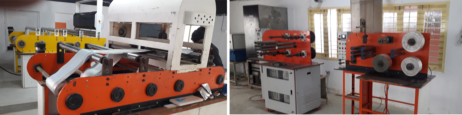
We offer a fail-proof transformer that matches the advancements and design challenges above. Our strong design capability includes the use of different forms of basic materials to fully draw their inherent characteristics, specific insulation materials, and customised CNC machine winding, which are proof enough to demonstrate our acceptability in the market with 1,000+ installations across India already.
Providing :
Utilising:
Which helps with:
Furthermore, the benefits of these, aiding in a real fail-proof transformer,
You can see, in an orderly manner, some of the aspects of magna's Fail-Proof Transformer basis, below:
This Fail-Proof Transformer is the basis for all the products of magna.
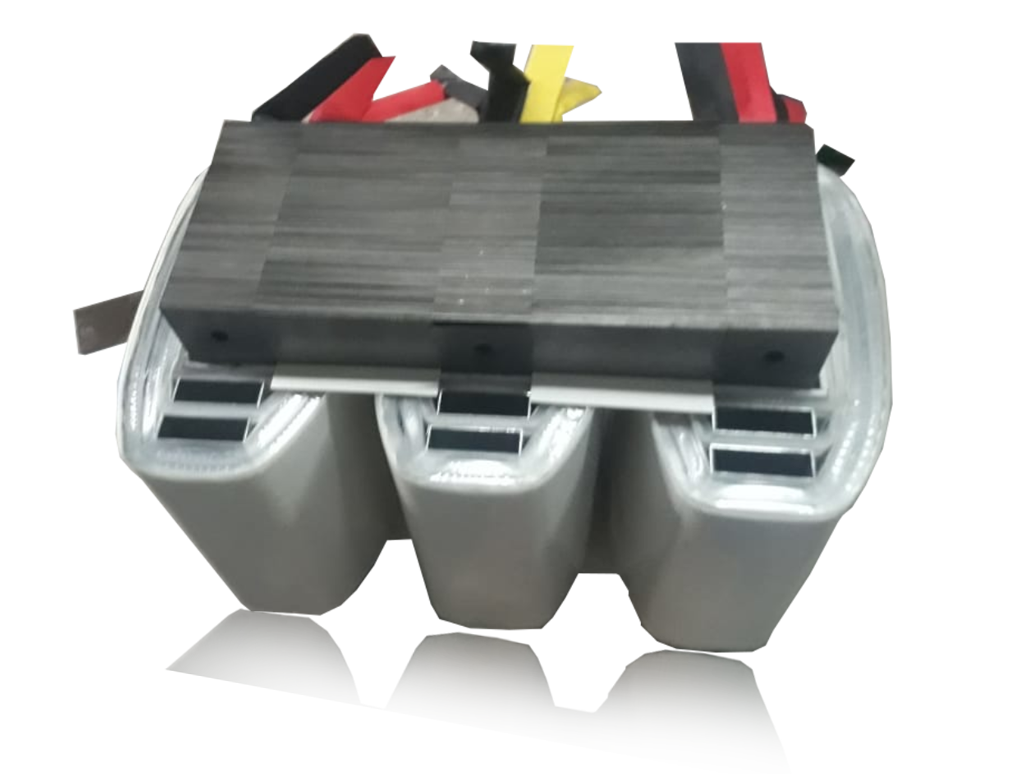
Aluminium-A++ Components
There are enough and more technical arguments with reference to the use of aluminium as a winding material as against copper. Many of the arguments have become inconsequential, and some are even considered misinformation in the context of their usage. See the table in the next column
Aluminium is the most abundant metal in the earth's crust. It ranks second, next only to steel, in terms of volumes used due to its versatility, which stems from its excellent and diverse range of physical, chemical, and mechanical properties. Aluminium, which is only one-third the weight of steel, is highly resistant to most forms of corrosion, is non-magnetic, non-combustible, non-toxic, and impervious (hence used in the food and packaging industries), and is also a superb conductor of electricity. Other valuable properties include high reflectivity and rapid heat dissipation. Because the metal is malleable, it is simple to work with in standard manufacturing and shaping processes.
India has the world's fifth-largest bauxite reserves, a raw material for aluminium production. .
In India, the electrical sector is the largest consumer of aluminium. The bulk of the aluminium used is in overhead conductors and power cables used in the generation, transmission, and distribution of electricity. Aluminium is used in switchboards, coil windings, capacitors, and many other applications as well.
Key factors that favour the use of aluminium .
While claims are made that aluminium has only 61% conductivity vis-a-vis copper, magna Aluminium Transformers use aluminium conductors with a larger cross-sectional area than copper. This covers the "equivalent conductivity losses" regardless of conductor material
Tensile Strength : The use of larger-sized conductors results in aluminium winding strength that is nearly equivalent to copper windings. The ability of a transformer to withstand the long-term mechanical effects of "high impact" loads depends more on adequate coil balance and lead support than on conductor choice. Therefore, there is no significant difference in tensile strength experienced between copper or aluminium transformers.
The use of correct hardware means that aluminium joints can be as good as copper joints in terms of quality, while also addressing the expansion effects of aluminium under changing temperatures.
Termination & Connection : The use of tin-plated aluminium lugs is widely recognised and has proven to be reliable throughout the more than 30 years that aluminium-wound transformers have been in use.
Last but not least, there is the cost of aluminium. It is far less expensive than copper, and more importantly, the price remains consistent in comparison to the volatility of copper's price. Due to scarcity, aluminium is also mined in India. Due to its rarity, copper is mined in only a few countries throughout the world. It is also more environmentally taxing for countries such as India. And savings in valuable foreign currency.
Aluminium is the most commonly used winding material for low-voltage, dry-type transformers larger than 15 KVA in several nations
The use of aluminium or copper foils results in a transformer with many advantages over conventional wire-wound versions:
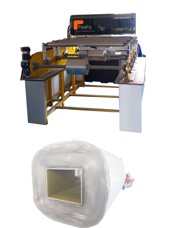
The basic transformer construction consists of electrical grade aluminium (or copper foil), temperature-suitable interwinding insulation, fiberglass, and Nomex sheet insulation. The complete unit is vacuum impregnated with a specially formulated epoxy resin developed to assist in heat transfer and bond the components into a stable, dense unit.
The use of strip foil conductors in large, high-power transformers to replace conventional round or rectangular magnet wire has been commonplace for many years.
The main advantage of using aluminium foil rather than copper in transformers is the reduction in weight.
Space Factor. The most efficient use of winding space is to layer wrap using magnet wire, as shown in Figure 1k. Depending upon the size of the wire used, there is a percentage of the winding area that cannot be used for the conductors..
This lost area is made up of the space between the wires and the insulation with which each wire is coated. As the voltage stress of the winding is increased, it is often necessary to add inter-layer insulation, creating more lost space and decreasing the available conductor area. The foil-wound coil illustrated in Figure 18 can be designed to make optimum use of the available winding area.
Each turn of the foil extends edge-to-edge of the coil and is separated from the next turn by one thickness of insulation.
There is no loss of winding space, which means that foil with the same circular mil area as wire will fit into a smaller winding area, or conversely, more circular mils of foil may be wound into the same winding area. operating
The temperature of the transformer affects its rating, efficiency, and voltage regulation. The current flowing through the resistance of the coil wire results in heat generation, which, plus the losses in the magnetic material, will increase the temperature. The temperature rise depends on how much and how fast the heat is generated and also how fast and efficiently this heat is wholly or partially removed.
Figure 2 shows to what surface temperature a black body would rise above ambient as a function of the watts per square inch of surface area of heat being dissipated into still air. The assumption is that all internal losses appear at the surface to be radiated into the ambient air.
If the heat transfer from the centre of the transformer is restricted, then the internal temperature will be hotter than the exterior, which will seriously affect the efficiency, regulation, and power rating.
So, a transformer design that reduces the rate of heat generation and/or increases the rate of heat transfer can result in a
A combination of any of the above is considered.
Magna Power Technologies Pvt Ltd is part of a Rs. 200-crore group and specialises in the design, manufacturing, and support of a wide range of power conditioning equipment.
23 samy street
, Muthu palaniappa nagar, Nagelkeni.
Chrompet. Chennai 600044
Phone : 9789146400
Mail : sales@magnapower.in